| Chapter 13. Developing ML Modules | ||
|---|---|---|
 |  | |
| Chapter 13. Developing ML Modules | ||
|---|---|---|
| | | |
Table of Contents
In the following chapter, the development of ML modules will be shown in three examples.
An ML module that allows adding a user-defined constant value to image voxels, see Section 13.1, “Creating a New ML Module for Adding Values”.
A more complex ML module that calculates a simple average over voxel values of an entire image, see Section 13.2, “Creating an ML Module For Simple Average”.
Combining the two ML modules in one project (which results in one DLL), with a discussion of the pros and cons of such combinations, see Section 13.3, “Combining Two Modules in One Project”.
The following examples are developed very explicitly to give you some insight into the ML, the MeVis image processing library. Another useful way to start with module development is to copy the source code of an existing module that might already have some of the wanted functionality and adapt it to your needs. For further information, please refer to the ML Guide.
![[Note]](images/note.png) | Note |
|---|---|
Developing C++ modules requires a C++ development environment being available on your computer, for example Visual C++ on Windows or Xcode on Mac OS X. |
| Note |
|---|---|
It is recommended to open and compile the debug versions for development. |
In the following chapter, we will create a new ML module with the functionality of adding a value to all voxels, in the following steps:
![[Tip]](images/tip.png) | Tip |
|---|---|
This example is delivered with MeVisLab ( |
First of all, make sure that you have a user package defined as described in Section 8.2, “Creating a User Package for Your Project” or create it now.
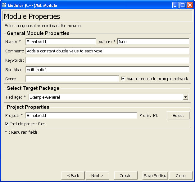
Then run the Project Wizard and select the link ML Module. This starts the Wizard for C++/ML Modules. Enter the following:
Name: SimpleAdd
Comment: Adds a constant double value to each voxel.
See Also: Arithmetic1
Target Package: Example/General
Project: SimpleAdd
Click Next to proceed.
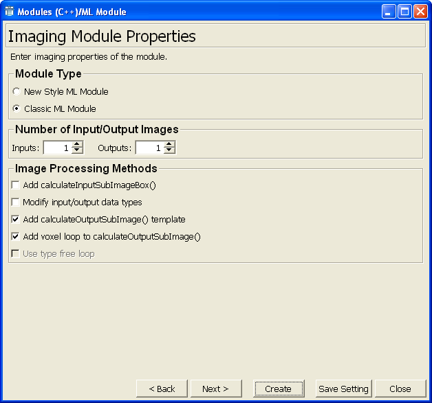
On the dialog Imaging Module Properties, the inputs and outputs as well as possible sample code can be added to the ML module.
Select the Module Type Classic ML Module. For information on the differences, see the MeVisLab Reference Manual, chapter “ML Wizard”.
Enter the following settings:
Inputs: 1
Outputs: 1
Check Add calculateOutputSubImage() template.
Check Add voxel loop to calculateOutputSubImage().
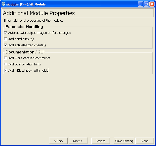
On the dialog Additional Module Properties, the inputs and outputs as well as possible sample code can be added to the ML module.
Make the following settings:
Check Auto-update output images on field changes (adds handleNotification).
Check Add activateAttachments().
Check Add ML window with fields.
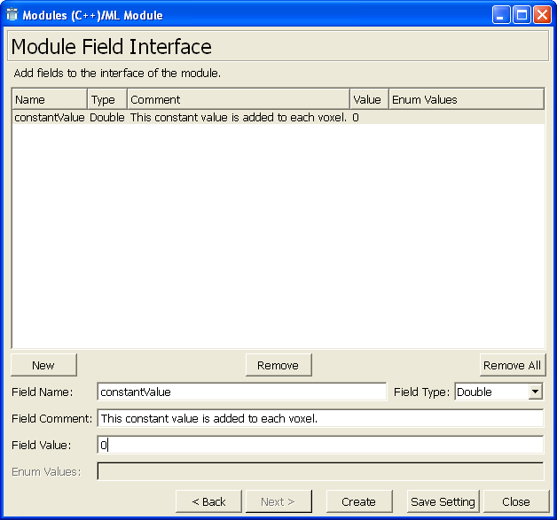
On the dialog Module Field Interface, the fields of the module can be defined (more fields can be added later but this is the easiest way to add fields).
Click New to create a new field, then enter the following:
Field Name: constantValue
Field Type: Double
Field Comment: This constant value is added to each voxel.
Field Value: 0.
Click Create to create the module.
In the default file browser of your system, two folders are opened:
folder with the source code: {packagePath}/Sources/ML/MLSimpleAdd
folder with the module's GUI definition: {packagePath}/Modules/ML/MLSimpleAdd
| Note |
|---|---|
For a full list of all created files and their contents, refer to the MeVisLab Reference Manual, chapter “ML Module — Created Files”. |
The foundation of the module has been created with the Wizard. From here on, the programming starts.
| Tip |
|---|---|
The Wizard will not close automatically. This way, you can change settings or fields and create the module once more. |
After module creation, the module database needs to be reloaded.
Out of the MeVisLab .pro files, the system-dependent project files (release and debug) have to be created. How this is done depends on your operating system.
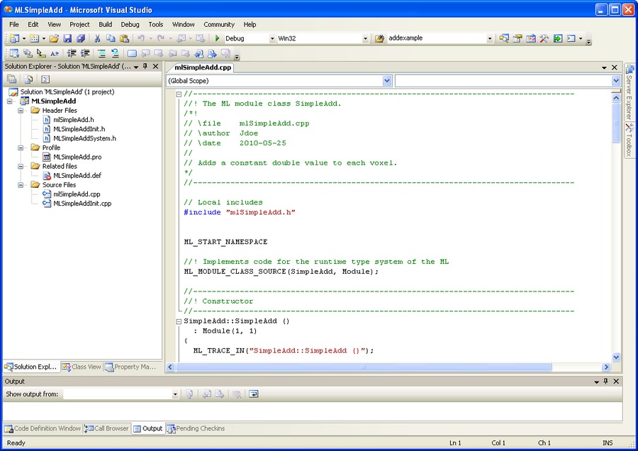
On Windows, the .vcxproj file should be created automatically. (If this does not happen, double-click the <ModuleName>.bat file to create one <ModuleName>.vcxproj project file (the debug/release status is set in the Visual C++ environment).
Double-click the project file. Visual Studio starts, displaying a list of all project files.
| Note |
|---|---|
If you encounter problems with MeVisLab on Visual C++ 2005, make sure that the Service Pack 1 (SP1) is installed. You can find all version-specific information on the MeVisLab website (http://www.mevislab.de/ ), section “Download”. |
On Mac:
Restart MeVisLab.
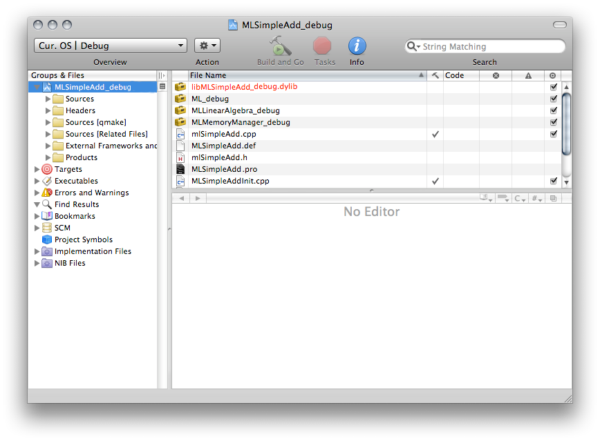
Double-click the <ModuleName>.pro file. The application MeVisLabProjectGenerator starts which creates the two files <ModuleName>.xcodeproj and <ModuleName>_debug.xcodeproj.
Double-click one of the project files (debug or release). The application Xcode starts, displaying a list of all project files.
On Linux:
Open a console with the required MeVisLab environment by running the mlshell script, for example $ /<MEVISLAB_INSTALL_PATH>/bin/mlshell
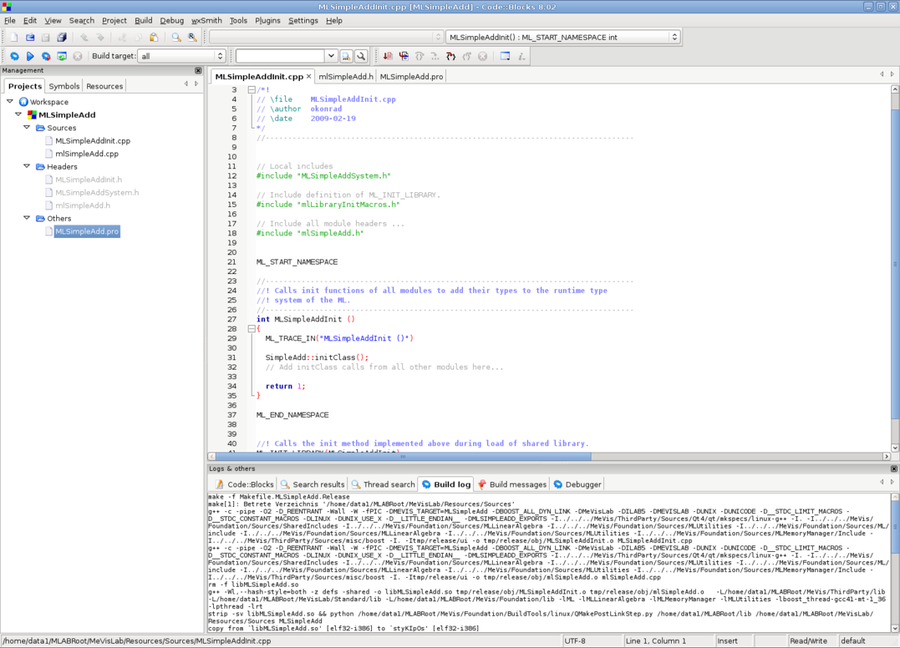
In the console, switch to the project folder and run the <MODULENAME>.sh shell script. This results in two files, Makefile.<MODULE_NAME> and <MODULE_NAME>.cbp. The .cbp file is a Code::Blocks project (see http://www.codeblocks.org/
for more information).
Here an example (execute this in a shell):
$ /home/john_doe/MeVisLab2.1/bin/mlshell
Running bash
$ cd /home/john_doe/MeVisLab2.1/MyUserPackageGroup/PackageName/Sources/MyModule
$ ./MyModule.sh
After calling
MyModule.sh you will have the Makefile.MyModule and MyModule.cbp in this directory. You can simply call
make -f Makefile.MyModule
to build the module, or use codeblocks to open MyModule.cbp and compile it from the IDE.
Before you can build your module, you must have created a user package and a module directory using the package wizard and module wizard respectively.
Open the file mlSimpleAdd.cpp.
| Note |
|---|---|
In the following code examples, the comment lines already available in the created |
As we add a constant value to each voxel, we need to adjust the value range of the output image, which results in:
  outMin = inMin + constValue
  outMax = inMax + constValue
In code, this is:
//----------------------------------------------------------------------------------
//! Sets properties of the output image at output outIndex.
//----------------------------------------------------------------------------------
void SimpleAdd::calculateOutputImageProperties (int outIndex, PagedImage* outImage)
{

  // get the constant add value
  const double constantValue = _constantValueFld->getDoubleValue();

  // get input image's min and max values
  const double inMinValue = getInputImage(0)->getMinVoxelValue();
  const double inMaxValue = getInputImage(0)->getMaxVoxelValue();

  // set the output image's min and max values
  outImage->setMinVoxelValue(inMinValue + constantValue);
  outImage->setMaxVoxelValue(inMaxValue + constantValue);
}
outIndex is the index number of the output connector.
Loop over all voxels of the output page and add the constant value. The loop is already generated by the wizard, so only the following line has to be added at the start of the method, to obtain the constant value in the correct data type:
  // Compute subimage of output image outIndex from input subimages.
  const T constantValue = static_cast<T>(_constantValueFld->getDoubleValue());
That is the datatype of the output image which is the data type of the input image.
Then change the inner line of the following loop from *outVoxel = *inVoxel0; to *outVoxel = *inVoxel0 + constantValue; so that the constant value is added to the value of the input voxel:
    // Process all row voxels.
    for (; p.x <= rowEnd;  ++p.x, ++outVoxel, ++inVoxel0)
    {
      *outVoxel = *inVoxel0 + constantValue;
    }
Compile the project (this includes all module files) in the development environment.
(Re)start MeVisLab.
| Note |
|---|---|
If the module was edited in the debug version, MeVisLab must be run in the debug mode. |
The restart is necessary
so that the ModuleName.def file can be found and parsed by MeVisLab.
so that the module DLL is copied to the correct location, from a temporary source folder to the lib folder. (If a .def file exists but no DLL is found, the module is displayed in red in MeVisLab.)
The module is now available in the (quick) search. Add it to the network.
For optimizing the GUI of the module — that is the panel — open the .def file. You can do that in two ways:
Open the .def file in your development environment. The downside is that the development environment does not support the MDL language of the .def file.
Open the .def file in the inbuilt text editor MATE, by right-clicking the module in MeVisLab and selecting Related Files → MLSimpleAdd.def from the context menu. The advantage is that MATE supports MDL (and Python and JavaScript). Therefore, it is recommended to edit MDL files primarily with MATE. (More information on MATE can be found in the MeVisLab Reference Manual, chapter “MATE”.)
Add the line
step = 100
to the definition of the field constantValue in order to adjust the
constant value conveniently. (Smaller steps are barely visible in the output.)
Window {
  Vertical {
    Field constantValue {
      tooltip = "This constant value is added to each voxel."
      step = 100   // big change for big effect
    }
  }
}
Reload the module definition by right-clicking the module and selecting Reload Definition from the context menu. This will only reload the GUI definition, not the module DLL.
To check if everything worked, double-click the module to open the panel and test
Congratulations, you have now implemented your first page-based and demand-driven ML image processing module!
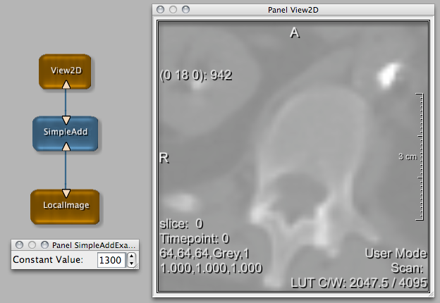
As last step, we will create a little example network.
Load the example network of the module via File → Open. Its name is automatically constructed as <ModuleName>Example.mlab. So far, the example network only includes the module itself.
Add two modules to the network, namely LocalImage and View2D. Connect the image input to the bottom connector and the image output to the top connector of SimpleAdd.
Double-click SimpleAdd to open its panel and View2D to open the viewer. When you now change the steps, the image display changes.
To create the help, right-click the new module and select Create Help from the context menu. The default HTML editor (as set in the MeVisLab Preferences) opens and displays a template HTML file. Add the module-specific contents and save them.
Now the module is ready for usage.
The module including the example network and help file are delivered with the examples of MeVisLab, so feel free to check it out and play around with it.
© 2013 MeVis Medical Solutions AG
| | | |
| 12.3. Programming Examples |  | 13.2. Creating an ML Module For Simple Average |