| 3.2. Module Network Panels | ||
|---|---|---|
 | Chapter 3. Modules and Networks |  |
| 3.2. Module Network Panels | ||
|---|---|---|
| | Chapter 3. Modules and Networks | |
A module can have a simpel panel that is rendered in the network and can show a dynamically updated information string and/or a button or checkbox.
This is useful to quickly access the state of a module or to trigger some functionality of the module without having to open the module's panel.
See Section 2.10, “NetworkPanel” for more information.
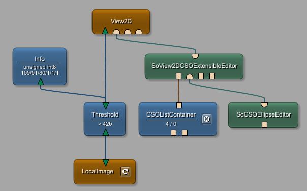
In the figure below, the Info module shows the image's data type and extent, the Threshold module shows the comparison operator and the threshold value, the LocalImage modules offers a button to reload the image, and the CSOListContainer shows the number of CSOs and CSOGroups and offers a button to remove all those objects.
© 2023 MeVis Medical Solutions AG
| |  | |
| Chapter 3. Modules and Networks |  | 3.3. Connector and Connection Types |