| 3.7. Module Halo | ||
|---|---|---|
 | Chapter 3. Modules and Networks |  |
| 3.7. Module Halo | ||
|---|---|---|
| | Chapter 3. Modules and Networks | |
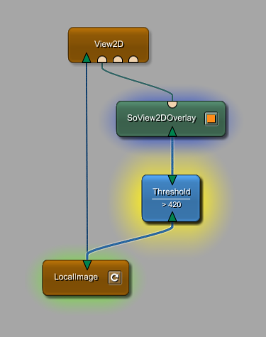
Selected modules come with what is called a halo effect. Two types are available: classic and alternative. The halo type is set in the Preferences, see Section 4.3.7, “Preferences — Network Appearance”.
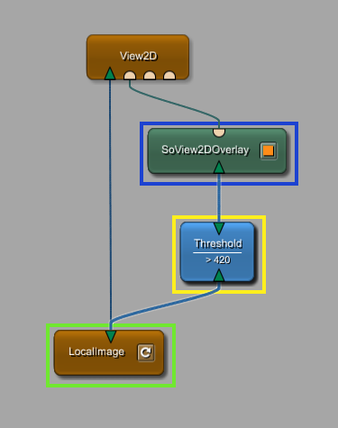
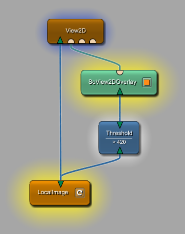
The classic halo shows a weaker halo for attached modules; the alternative halo shows the same strength for all modules. For the selected and the attached input and output modules, different colors can be set in the Preferences to make their roles more visible.
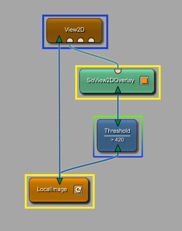
If an attached module is input and output module of selected modules at the same time, the halo color will mix. With classic halos, those modules have a white halo. Alternative halos are rendered in both colors as shown in the right figure.
© 2023 MeVis Medical Solutions AG
| |  | |
| 3.6. Mouseover Information |  | 3.8. Module Highlighting |