| 3.7. Module Handling | ||
|---|---|---|
 | Chapter 3. Modules and Networks |  |
| 3.7. Module Handling | ||
|---|---|---|
| | Chapter 3. Modules and Networks | |
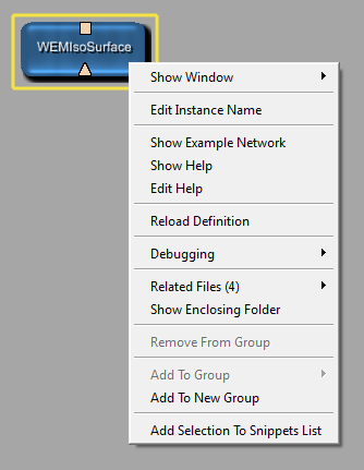
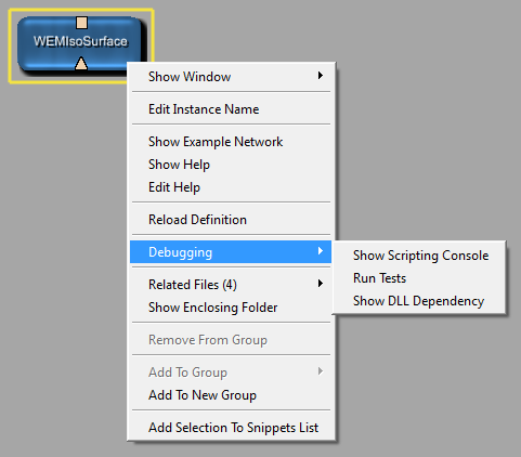
Right-click modules to open the module context menu. Its contents slightly depend on the module type. Available groups of entries:
Open Inventor only: Section 26.8, “Set Open Inventor Override Flag (Inventor Modules)”
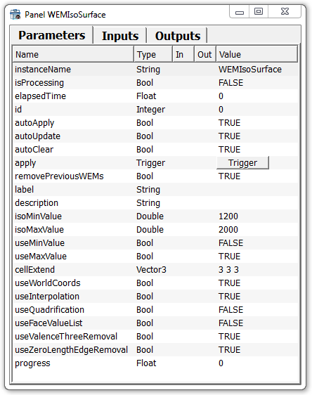
Each module has at least one panel, the automatic panel which is a list of all fields and parameters of the module. Use it for an overview or for editing the parameters (see also Section 10.1, “Fields”).
![[Tip]](images/tip.png) | Tip |
|---|---|
Refer to chapter Section 25.3, “Module and Network Handling — Shortcuts and Tricks (All Platforms)” for a shortcut for opening a module's automatic panel. |
The automatic panel lists all fields of the module in order of their initialization in the C++ code. It also shows the data type of the field, whether it is an input or output field, and its current value. The value can be edited directly on the automatic panel.
| Tip |
|---|---|
The header of the list of fields of the automatic panel has a context menu where you can toggle how to sort the fields or to turn off the sorting at all. In the later case, the fields are ordered as they are implemented in C++ or in the script. An option 'Show Attribute Column' turns on an otherwise hidden column where non-persistent and non-editable fields are marked with 'p-' and 'e-', respectively. |
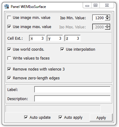
Typically, another type of panel is also available, which shows the parameter fields in a layouted style. It is written in MDL. Important points:
It is possible to add fields that are not in the C++ code.
It is possible to add field listeners that can trigger script code.
It is possible to keep rarely used fields out of the layouted panel. This way, the panel usability might be enhanced. (Fields can always be edited in the automatic panel.)
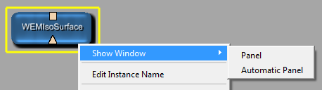
Other windows may be available. For example, for the View2D module, a Viewer and a Settings window are available. For information on defining windows, see the MDL Reference, chapter “1.3.2.1. Window”. For an example, see the Getting Started, chapter “Adding the Macro Parameters and Panel”.
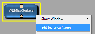
This option allows distinguishing several instances of the same module. Within a network, each module instance must have a unique name. If no specific instance name is given, the copies of the modules are numbered automatically (1, 2, 3, etc.). Alternatively, the instance can be renamed manually.
![[Note]](images/note.png) | Note |
|---|---|
Instances of modules have to be unique because modules are addressed by their instance names in scripting. |
Select the option or use the respective shortcut (see Chapter 25, Shortcuts) to open a dialog for entering a new instance name.
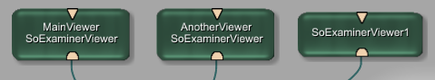
The instance name is displayed above the module name. If the module instances are numbered, only the instance name is displayed, since it includes the module name.
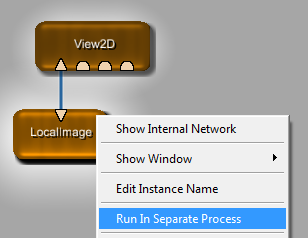
Run In Separate Process
This is an experimental feature which allows moving ML and macro modules to a worker instance of MeVisLab that is automatically started in the background. Field and image changes are transmitted asynchronously between the main instance and the worker instance. This feature can be used to move long running calculations into the background without blocking the GUI, for example.
| Note |
|---|---|
Restrictions:
|
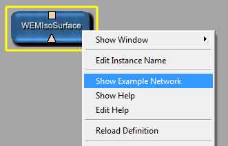
Show Example Network
Opens the example network in a new network tab. Only active if an example network exists (otherwise the entry is grayed out).
If a module has multiple example networks, this entry is a menu item, showing the number of example networks. On selecting, a subnetwork offers all available example networks by their names.
Show Help
Displays the HTML help file for the module in the default browser. Only active if a help file exists.
Edit Help
Edits the mhelp file in MATE. Use this option if fields have changed (renamed, new fields, removed fields) or if the module is new.
Reloads the module definition (.def file). This is necessary when layouting panels and windows or when working on the scripting.
| Tip |
|---|---|
A single selected module can also be reloaded by pressing the according shortcut key for the OS. Refer to Section 25.1, “Shortcuts on Windows and Linux” and Section 25.2, “Shortcuts on Mac OS X”. |
If modules are being reloaded, an animation (module turns white and slowing gains its color back) indicates that the modules' definitions are indeed being reloaded.
In the Debugging submenu, helpful options are available.
Show Scripting Console
Opens the Scripting Console for scripting in the context of the current module, see Section 19.1, “Scripting”.
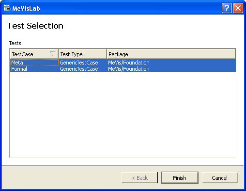
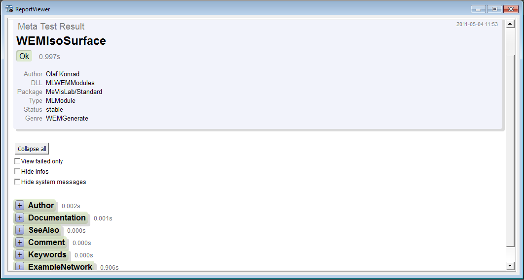
Run Tests
Starts the TestCenter for the module. Test cases associated with the module(s) are listed here. In case of WEMIsoSurface, only the two generic test cases “Formal” and “Meta” associated with all modules are available. When Finish is clicked, the test cases are run and test reports are available. (See also Section 4.6.4, “Run Module Tests”, the TestCenter Reference, and the Getting Started, chapter 16, “Using the TestCenter”.)
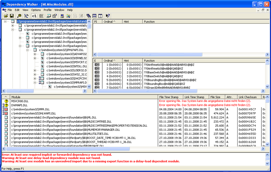
Show DLL Dependency (Windows only; not for macro modules)
This option uses the Dependency Walker for checking and displaying all dependencies for the module. For more information, please refer to the help of the Dependency Walker.
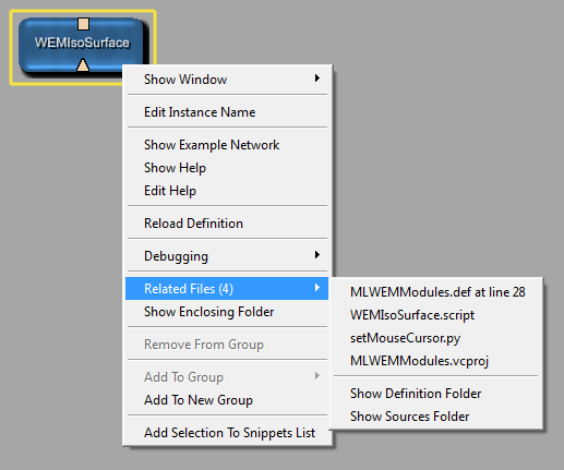
Related Files: Lists all files belonging to the module. Possible file types are .def/.script (MDL definition files), .vcxproj (VC++ project files on Windows), and .py / .js (scripting files). Select a file to open it in the default editor (as set in Section 4.3.4, “Preferences —
Supportive Programs”).
Show Definition Folder: Opens the definition folder of the module which contains the .def and the .script file. If the module is augmented by scripting, the .py or .js files can also be found there.
Show Source Folder: Opens the folder containing the source code files of the module.
For the Groups functions, see Section 3.9, “Using Groups”.
Adds the selected module(s) to the Snippet List, see Chapter 22, Snippets List.
Modules may have more inputs and outputs than visible at first, to keep the module display as uncluttered as possible. An example for a module with possibly hidden inputs is the View3D module. It offers the additional context menu entry View3D Options → Show Inventor Inputs. If selected (default), three Inventor input fields are displayed. The option can also be selected in the Settings panel.
| Tip |
|---|---|
The three Inventor inputs of |
Depending on the programming, the number of inputs may be dynamically set. For example, this is the case for the Switch module.
For a supporting visualization while interactively drawing connections, see Section 3.2, “Connector and Connection Types”
In the context menu of macro modules, the option Show Internal Network is available. If selected, the network of the macro is opened on another network tab.
| Tip |
|---|---|
Refer to chapter Section 25.3, “Module and Network Handling — Shortcuts and Tricks (All Platforms)” for a shortcut to open a macro's internal network. |
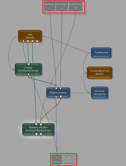
The pseudo-connectors shaded in gray are placeholders and indicate the input (bottom) and output (top) parameters of the macro, which constitute the connectors of the macro module. They are automatically drawn at the edges of the bounding box of the network. Important points about them:
They cannot be moved or removed interactively but can only be changed in the script.
They cannot be selected in a rectangle but each of them can be clicked, in which case the input/output square, the connection(s), and the connected module(s) are highlighted.
| Note |
|---|---|
Modules in an internal network of a macro that are connected to the macro's input / output fields (visualized by being connected to the pseudo-connectors) cannot be removed interactively from the network. On an attempt to remove such a module, a window with a warning pops up. If such a module needs to be removed, the according connection needs to be removed in the scripting and the macro reloaded first. |
If the macro module only has inputs, only those are drawn. An example for inputs only are the View2D and View3D modules.
| Note |
|---|---|
The tab of the internal network remains connected to the module from which it was opened. When the module is deleted or its network closed, the internal network is also closed. |
© 2013 MeVis Medical Solutions AG
| |  | |
| 3.6. Module Highlighting |  | 3.8. Network Handling |